Many factors need to be considered when safely setting-up mobile cranes on site. Crane stability often depends on the integrity of the ground on which it stands. Effective assessment of ground conditions is essential to assist with the safe set up and operation of cranes. To reduce the risk of crane accidents as a result of improper crane set up, planning activities shall be carried out by a competent person(s) to assess the capability of the ground to withstand the loads and pressures imposed by the lifting equipment.
All parties who are involved in the planning, set up and use of cranes on site must be aware of the fundamental criteria, planning issues, and risk assessments that are needed to ensure lifting operations proceed in a safe and stable manner.
This Guidance Note provides general guidance to assist on:
- determining the load exerted by mobile crane outriggers or crawler crane tracks
- determining the suitability of the crane mats, and
- bearing capacity of different types of soil.
Responsibility
As with all activities on construction sites, the effective management of the safety of lifting operations can only succeed if all parties involved are clear about their roles and responsibilities. It is essential for all persons undertaking these roles to be competent, having relevant up-to-date training and the qualifications and experience appropriate to the operations for which they are responsible.
The responsibilities for undertaking the various activities involved in the ground assessment are set out below:
- A person conducting a business or undertaking (PCBU) that includes the carrying out of construction work (i.e. the principle contractor in control of the project site) has overall responsibility for the safety of all personnel on site. They should ensure that where a crane is being used to carry out a task, adequate steps have been taken to ensure the stability of the crane during transport onto site, set up, use, movement, maintenance, dismantling and removal from the site. PCBU should provide accurate geotechnical report for the site ground condition or other relevant information for crane stability to the worker responsible for the lifting operations if this is necessary for the safe operation of the lifting activity. It is usually the PCBU’s responsibility to make sure the ground is safe to work on.
- A worker who carries out work for a PCBU (i.e. the person or company in control of a lifting operation) is responsible for all aspects of planning, supervision and execution of the lifting operation, including ensuring that the ground or structure on which equipment stands will take the loads imposed by the plant. This does not mean that the worker has to be an expert in ground assessment, they must however take reasonable steps to satisfy themselves that the information provided by the person in control of the site is relevant and appropriate. The worker should have the necessary confidence and authority to carry out their duties effectively and safely.
Where doubt exists as to the accuracy or sufficiency of the information provided it is the responsibility of the worker to ensure that the lifting operation does not proceed until the doubt has been satisfactorily resolved.
Loads and Forces
Assessment of loads and forces imposed by the crane on the ground shall be conducted during the planning stage. The following loads and factors should be considered when assessing load and forces.
1- Crane loads
Information on crane loads and forces can be found from sources including technical data published by the manufacturer. Different rigging configurations of the crane, i.e. using different combinations of counterweights or fly jibs in the lift operation may associate with different crane weight distribution. Refer to the manufacturer data to determine what rigging configuration is representative and what weights and loads apply. Information on the individual weight and center of gravity of the crane components should be obtained and applied in the load calculations.
2-Rigging gear
The correct weight of lifting accessories such as chains, shackles, spreader bars, etc. shall be added up and included as part of the vertical load when calculating loads and forces.
( know how to prepare Critical lift plan )
3- Object loads
Always obtain accurate information (weight, density, overall dimensions, and center of gravity) about the load to be lifted, do not guess, and do not use the crane as a ‘weighing scale’.
( Read more: Rigging and load calculation overview)
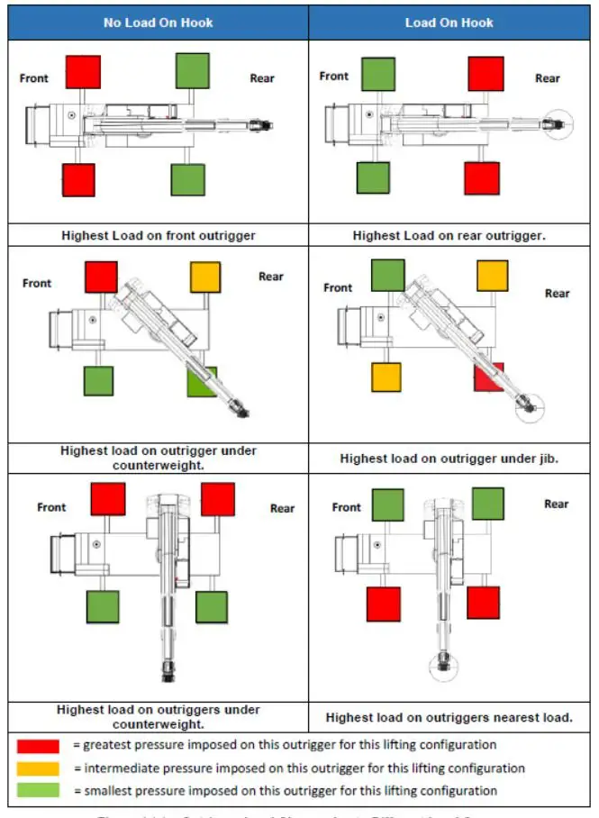
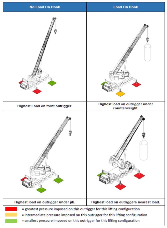
4 – Load cases
Different load cases can impose different loads and forces on the ground (see Figure 1 and Figure 2). During the lift operation, crane boom length, slew angle, and slew arc may vary, these will change the forces on the outriggers. It is often assumed that the maximum loads and forces will occur during operation at maximum capacity, this is not always the case, for example, outrigger loads could be at their highest without any load on the hook at minimum radius due to backward moment from the counterweight [1]. In some load cases, the total load of the crane may be imposed largely on one outrigger or one crawler track when the boom or counterweight is slewed over that outrigger or over the side of that track.
5- Calculation
Calculation of the load exerted by the crane outrigger or track should consider both the vertical load (from the crane loads, rigging gear loads and object loads) and the load caused by the moment acting on each outrigger or track under different load cases (see Figure 1 and Figure 2).
In addition, other loads to consider include:
- dynamic loading due to wind pressure
- lateral loading due to incorrect set-up or different settlement of supports
- dynamic loads caused by slewing or a swinging lifted load
- dynamic loads caused by crane travelling with load
- emergency loads


6- Lifting on rubber
Crane operated without the outriggers extended is referred to as “operating on rubber”. When operating on rubber, follow the setup procedure and operating limitations specified by the crane manufacturer. On rubber, a load chart shall be used if operating on rubber. Tire conditions need to be properly checked and tires need to be inflated per the manufacturer’s specifications.
Where the load will be picked from and where it will be placed must also be considered, so ground conditions for the picking and placing area can be assessed.
7- Articulated crane
It is recommended that articulated crane loads should be calculated or checked by an engineer through theoretical calculation. Refer to Appendix A for reference for articulated crane axle loading.
8- Manufacturer’s software
Many crane manufacturers supply software and tables that can give accurate and comprehensive load data when these resources are used properly.
9-Theoretical calculations
Although manufacturer’s software is a good resource to use, theoretical calculations are useful for checking the computed results to make sure the resources are properly used. Theoretical calculations can account for conditions not considered in the manufacturer’s software or for where the crane model is not covered by the manufacturer’s software.
It is recommended that theoretical calculations of crane loads for different load cases should be done by a competent person (i.e. qualified engineer).
Crane Mats
Crane mats (timber, steel, HDPE, etc.,) are used to distribute the load of the crane to the ground. The suitability of the crane mat used is determined by:
- the size of the mat is suitable to distribute the load to the ground at a stress level less than the ground bearing capacity and
- the strength and integrity of the mat and its ability to handle the load exerted by the crane.
1-Crane mat size calculation – uniform pressure Unit convert:
1 t/m2 = 10 kPa
Mass and pressure unit convertor and ground pressure calculator are available in:
CICA-CS-0020-0 Multi-crane or Multi-hoist Lifting
Example 1
If crane load and crane mat size is known, the pressure imposed by the crane on the ground can be calculated by:
Pressure = Force/Area
This pressure is then compared with the maximum permissible ground pressure to check whether the mat size is suitable for the lift.
For example, if the lift study indicates that a crane imposes a maximum load of 48 tonnes on the outrigger, and the available crane mat size is 1.7m x 1.7m. Then the pressure imposed by the crane to the ground can be calculated by:
Force = 48 tonnes x 9.8m/s2 = 470.4 kN
Area of the crane mat = 1.7m x 1.7m = 2.89 m2
Pressure = 470.4 kN/2.89 m2= 162.8 kN/m2
If the maximum permissible ground pressure is 200kPa, then the crane mat size is adequate for the lift.
Example 2
Crane mat size can be calculated by dividing the crane load by the maximum permissible ground pressure.

For example, if the lift study indicates that a crane imposes a maximum load of 48 tonnes on the outrigger, and the maximum permissible ground pressure is 200kPa. Then the size of the crane mat can be calculated by:
Force = 48 tonnes x 9.8m/s2 = 470.4 kN
Maximum permissible ground pressure = 200kPa =200 kN/m2
Required mat bearing area =470.4kN/200kN = 2.35 m2
2- Crane mat strength and stiffness
Not only do crane mats used for distributing outrigger loads need to be suitably sized they also need to be strong to withstand the load imposed by the crane outriggers.
The strength and stiffness of the crane mats will depend on the material and the thickness. Shear strength, bearing capacity, and bending strength should be checked for the selected crane mats.
For timber mats, good quality timbers should be used. Shear stress is critical for timbers, if excessive, the timber can crack, sharply reducing resistance to bending and inviting failure. Timber bending strength and bearing capacity should also be checked. For crane mats made of other materials(steel), refer to the manufacturer’s specification on bending strength and bearing capacity. It’s also important that the load is placed in the center of the pad and away from the edges. If the load is placed too close to one side it has the effect of concentrating the load on a smaller area, resulting in excessive deformation and possible collapse
Ground Condition
1- Ground capacity
Prior to setting up a crane on-site, the ground condition should be reviewed in the risk assessment process to determine whether the ground is suitable to operate the crane safely and ensure crane stability.
It is recommended that the ground condition be inspected by a geotechnical engineer to provide accurate permissible ground pressure. Crane lift study results should be provided to the geotechnical engineer and a geotechnical report should be issued by the geotechnical engineer with instruction on the suitability of the ground at the time of the lifting activity conducted.
The report should provide inspection results of the bearing capacity of the ground including surface conditions as well as layers of the ground under the surface that could influence ground bearing capacity. The ground can have weak layers below the surface and these underlying layers of weak or soft ground can possibly lead to a collapse. The report should also outline the estimated settlement due to the load and whether the settlement would cause any instability of the crane during the lift.
If the ground is found to be not suitable, additional measures must be taken before proceeding with the task. These may include but are not limited to:
- design measures to reduce imposed loads, i.e. re-selection of the crane, repositioning of the crane, reduction of task loads (e.g. splitting of loads), re-sizing of the crane mat used.
- design measures to ensure ground suitability, i.e. soil stabilization, grouting, dynamic compaction.
Table 2 below listed typical maximum permissible ground pressure for different ground types as a reference

2-Trench diagram
When outriggers exert pressure on the ground, it is important that the outrigger feet do not sink into the ground, or cause nearby excavations to collapse – as this could lead to the crane tipping over.
Outriggers put stresses onto the ground beneath them, sometimes called the “zone of influence” as shown in Figure 3. As a rule of thumb, assume that the zone of influence works at a 45° angle or one meter from top whichever is the greater. This angle can vary depending on the nature of the ground beneath the outrigger and the design of the outrigger support. Further investigation by an engineer may be required when ground conditions are unknown, or when clarification is needed on the rule of thumb.
When it comes to setting up a crane near a trench, always set up a crane, so that the nearest outrigger to a trench, is at least as far away from the trench, as the trench is deep. This rule assumes a zone of influence working at a 45° angle (Figure 4).

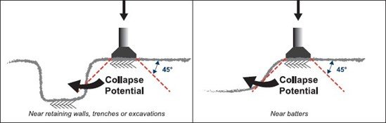
Figure 4 Trench Diagram


11 thoughts on “Guideline for Crane Stability and Ground Pressure”