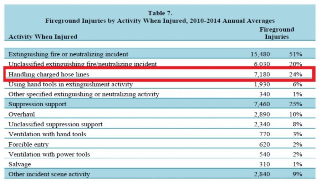
NFPA reports suggest that there are on average 13,795 firefighting Injuries annually associated with handling charged hose lines, some of them fatal or life-changing.
With the plant size ever-growing, the firewater system pressures are increasing in order to reach farther, however, if this high pressure is passed through the hydrant valve unregulated it poses a significant threat to the firefighter.
This threat increases exponentially if the firefighter is inexperienced or is experiencing fatigue due to handling a high-pressure hose for an extended period of time.
NFPA 14 clause 7.2.3.1 states that residual pressure at the outlet of hydrant valve must be limited to 6.9 bar and if this residual pressure exceeds 6.9 bar, the system design should include a listed pressure regulating device.
NFPA report “Patterns of Firefighter Fireground Injuries – Dec 2016” states that 24% of the injuries occurred while handling charged hose lines.
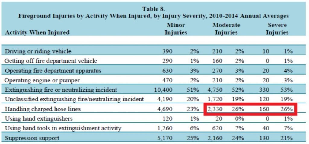
Out of these injuries, over 50% ranged from moderate to severe. Introduction Pressure-regulating
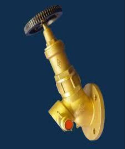
Pressure-regulating Hydrant Valves are used for controlling pressure during fire hydrant operation to ensure the safety of the firefighters handling the hose. Any surge in the inlet pressure is regulated by the valve’s internal mechanism down to the safe predetermined outlet pressure. The outlet pressure can be set within the range of 3.5 bar – 9 bar at the factory or at the site without the requirement of any special tools.
A pressure regulating hydrant valve is different from a pressure-reducing valve since the former offers a fixed outlet pressure irrespective of the varying inlet pressure, on the other hand later only offers a pressure differential which means the outlet pressure will increase with subsequent increase in inlet pressure. Oil, Gas & Petrochemicals Operators Using Pressure Regulating Hydrant Valves Currently:
- ADNOC Onshore
- ADNOC Offshore
- PDO
- ENI
- BP
- ORPIC
- Bahrain LNG
- Petronas
- Chevron
- Qatargas
- Husky Energy
Technical Data
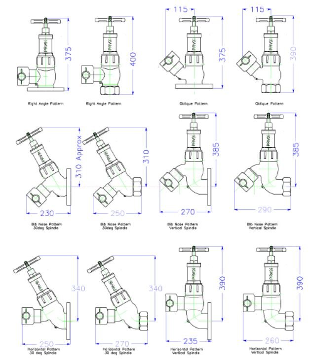
Pressure Regulating Hydrant Valves are manufactured in the following configurations:
- Patterns:
- Bibnose
- Oblique
- Right Angle
- Horizontal or Straight Through
It is the end user’s prerogative to decide the pattern they might require based on their experience and site conditions.
Inlet Connections:
- Flanged (Class 150 and Class 300)
- Threaded
Inlet Sizes: 1 ½”, 2”, 2 ½” , 3” & 4”
Outlet Connections:
- BS 336 Instantaneous
- Storz
- Threaded
- AFNOR
Rating: 25 bar (Maximum, Limited by the Inlet and Outlet Connection)
Material of Construction:
For seawater applications or where seawater is to be used as back up for freshwater, it is imperative that Aluminium Bronze wetted parts to be used to avoid corrosion.
Internals: Aluminium Bronze wetted parts.
Body
Standard – Gunmetal LG2 BS 1400 (BS EN 1982 CC491K)
Alternatives – Aluminium Bronze AB2 BS 1400 (ASTMB505-C95800)
Main Shaft and Shutdown Spindle – Alternatives in Monel K500
Approvals: FM approved
Advantages
- Safety – Offers means of safety to the firefighters in case of the sudden surge in pressures.
- Ease of Maintenance – The valve can be serviced in situ without having to remove it from the line which means the hydrant valve remains active even during maintenance.
- Longer Life Expectancy – Superior grade material (Gunmetal body and Aluminium bronze wetted parts) offer longer life even in the harshest of conditions irrespective of the kind of firewater in use (Sea Water / Brackish Water /Fresh Water).
- Lower Life Cycle cost – Ease of maintenance and longer life offers substantial savings in terms of product life cycle cost.
Shown below are some typical valve configurations