No chemical process facility is immune to the risk of over-pressure to avoid dictating the necessity for over-pressure protection. For every situation that demands safe containment of process gas, it becomes an obligation for engineers to equally provide pressure-relieving and flaring provisions wherever necessary.
The levels of protection are hierarchical, starting with designing an inherently safe process to avoid over-pressure followed by providing alarms for operators to intervene and Emergency Shutdown provisions through ESD and SIL rated instrumentation.
Beyond these design and instrument-based protection measures, the philosophy of containment and abatement steps such as pressure-relieving devices, flares, physical dikes, and Emergency Response Services is employed.
HIGH INTEGRITY PRESSURE PROTECTION SYSTEMS (HIPPS) ARE RELATED TO THE THIRD LAYER OF PROTECTION WHEREBY PROCESS SHUTDOWN CAN BE INITIATED BY SHUTDOWN VALVES THAT RECEIVE INSTRUCTIONS FROM A LOGIC SOLVER WHICH IN TURN ARE FED BY PRESSURE TRANSMITTERS.
In the oil and gas industry, process facilities are often subjected to erratic fluctuations in wellhead pressure and flow trends. Such process systems in recent years are tended to for over-pressure protection with the installation of HIPPS.
HIPPS aid in shutting down well heads instead of having to flare sour gas through pressure-relieving devices that are subsequently routed to a flare system.
Introduction
With world gas demand increasing steadily over the years, High-Pressure High Temperature (HPHT) environments are also increasingly becoming common. Standard design methods involve designing the entire well head to export systems to fully-rated conditions (1500#, 900#, etc.) depending on the operating pressures and temperatures.
However such methods would unnecessarily increase project costs and affect installation foot print depending on how flammable or toxic is the process fluid, sometimes to the point of not giving any viable cost benefits.
To attend to such un-viable scenarios, the concept of de-rating Non-HPHT equipment in downstream operations with over-pressure protection can be employed. For these purposes, HIPPS is treated as a Safety Instrumented System (SIS) that is based on a Safety Integrity Level (SIL).
From a SIL perspective, HIPPS follows a minimum of SIL 3 rating where the Average Probability of Failure on demand is of the order between >=10^-4 to <10^-3. It must be noted that HIPPS is an SIS that aids more as risk reduction for preventative measures rather than a risk mitigation measure.
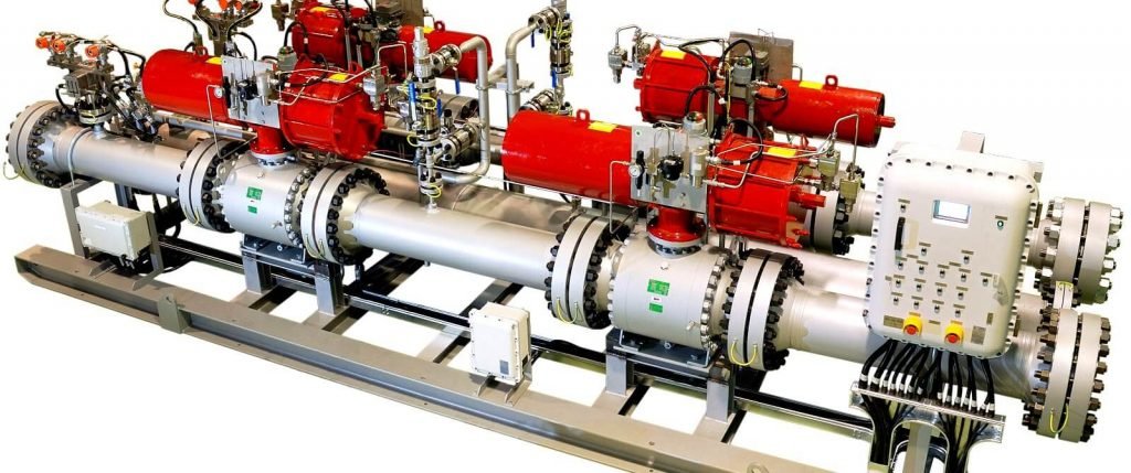
The typical architecture of HIPPS is shown in the Figure below.

HIPPS Operating Philosophy
A typical HIPPS architecture consists of three (3) pressure transmitters (PT) that constantly record the line pressure which is fed to a logic solver. In the event of an over-pressure, the logic solver initiates a shutdown operation of two (2) consecutive Fail-close (FC) valves which are installed on the same line thereby shutting down fluid flow.
A pressure alarm (PA) serves the purpose of informing the operation personnel.
The purpose of installing the said number of transmitters and valves are as follows,
To avoid compromising the HIPPS functionality due to the failure of any one shutdown valve (SDV), a second valve is added to provide higher redundancy. Both valves are operated on a 1oo2 voting philosophy that decides which Fail-Close (FC) valve closes.
To avoid receiving a premature or false signal from the pressure transmitter, a 2oo3 voting philosophy is employed as against a 1oo3 voting philosophy. This means that unless 2 pressure transmitters concur that there is an overpressure scenario, HIPPS is not activated.
HIPPS Valve Selection
HIPPS valves can be operated hydraulically or by solenoid methods. The two (2) types of valves used are either ball type or butterfly type. Ball valves provide the best shutoff conditions and can range from 2 inches to 56 inches depending on the manufacturer. Whereas butterfly valves can be provided from 2 inches to 100 inches, again depending on the manufacturer.
For HPHT applications, the piping class can vary from as high as 2500# which can be provided in the ball class range with material ranging from carbon steel, stainless steel, duplex as well as special alloys.
THE TYPICAL STROKE TIME FOR HIPPS VALVES SHOULD BE OF THE ORDER OF <2 SEC. VALVE SELECTION MUST ALSO CONSIDER THAT HPHT APPLICATIONS CAN WITNESS TEMPERATURES AS HIGH AS 500 DEG.C. HIPPS VALVES MUST ALSO BE ABLE TO CATER TO PARTIAL STROKE TESTING CAPABILITY (PST), TIGHT SHUT-OFF (TSO) (E.G., CLASS V OR CLASS VI OF ANSI FCI 70-2), FAST ACTING, FIRE SAFETY TESTED TO FOR EXAMPLE, API 607. ENVIRONMENTAL CONSTRAINTS MUST ALSO BE MET FOR FUGITIVE EMISSIONS SUCH AS ISO 15848-1 STANDARDS.
HIPPS Engineering Standards
HIPPS can cater to many applications such as offshore/onshore well heads, flare headers, and chemical process industries. ASME Section VIII, UG-140 (Over-pressure Protection Systems) provides a range of applications for which HIPPS can be used, such as,
High Propagation Chemical reactions resulting in loss of containment prior to the relief device opening or processes that yield impractical large vent areas
Runaway Polymerization, Exothermic or Reactive reactions that produce large vapor rates rendering relief devices insufficient to cater to over-pressurization scenarios.
To keep the article brief, the focus is made on Oil and Gas applications. HIPPS for the Oil and Gas industry is based on two aspects – prescriptive and performance-based.
Standards such as API, ASME, ANSI to suggest a few are for design, manufacture, and implementation and examples are API 14C (Recommended Practice for Analysis, Design, Installation, and Testing of Basic Surface Safety Systems for Offshore Production Platforms), API 6A (Specification for Wellhead and Christmas Tree Equipment) for offshore applications, API 520/521, API 17O (Subsea High Integrity Pressure Protection Systems – HIPPS) to name a few.
The other aspect is the IEC standards, chiefly IEC 61508 supplemented by IEC 61511 which are more of performance-based standards that describe how to arrive at a solution rather than prescribing a solution.
This would leave room for elucidation between different operators, contractors, and suppliers thereby resulting in a lack of commonly accepted industry specifications. The IEC 61508, for example, focuses much on the functioning of the logic solver and touching minimally on the final control element.
These gaps left in IEC 61508 regarding final control elements such as valves and solenoids are covered in IEC 61511.
IEC PROVIDES SIL RATINGS WITH PROBABILITY OF FAILURE ON DEMAND (PFD) AND RESPECTIVE ARCHITECTURE NOT FOR INDIVIDUAL COMPONENTS, BUT FOR THE SYSTEM AS A WHOLE WHICH MUST INCLUDE THE ACTUATORS, INITIATORS, FINAL CONTROL ELEMENTS AND LOGIC SOLVERS.
When different manufacturers assume certain architecture for HIPPS components provided, the individual components Probability of Failure on Demand (PFD) would not necessarily represent the overall system’s PFD which is used to define the SIL rating.
Therefore the PFD for a SIL assessment needs to always be investigated on a case to case basis prior to understanding the limitation on the SIL rating arrived at.
Pressure Relieving Devices vs. HIPPS
A point of contention arises when one asks if when a piece of equipment is equipped with multiple relieving devices to deal with over-pressure scenarios, wherefrom arises the necessity to install a HIPPS. To suggest so means a justification is required to install HIPPS.
For any successful implementation of HIPPS, an examination of applicable regulations, standards, local codes, and insurer’s requirements that may mandate the need for relieving devices is required. This is to be followed up by a Hazard Analysis (HAZAN) by a multi-disciplinary team.
The process risk needs to be evaluated based on frequency and consequence such that the HIPPS proposed can demonstrate that the mitigated risk is lower than the risk tolerance criteria, to allow for the removal of associated relief devices from flare load calculations.
Traditionally, pressure vessels are equipped with pressure-relieving devices that are routed to an industrial flare. However, when the flare load capacity is insufficient to deal with excess capacities, HIPPS offers the advantage of risk reduction, for example, shutting down well heads in oil and gas applications. But this also obliges the engineer to ask, if when a HIPPS system is installed, does it always necessitate pressure-relieving devices to be installed as well.
Pressure vessels that operate above atmospheric conditions of 15 psig are designed as per Code ASME Section VIII Division 1 and to cover matters of overpressure protection, UG-125 to UG 140 of the said code provides basic requirements. The ASME UG-140 requirements and procedures are commonly known as Code Case 2211.
The requirements of a relief device covered by UG-125 to UG-138 are to be designed as per API 521. For cases where the requirement of a relief device can be overcome is based on UG-140(a) and UG-140 (b) of the said code which pertains to Inherently Safe Design and HIPPS based design under specific cases respectively.
Industrial use of HIPPS certainly provides the option of installing a smaller sized relieving device but cannot eliminate the necessity of relieving devices, although in certain specific cases, the need for PRV’s can be eliminated.
As per API 521 and Code Case 2211 of ASME Section VIII, Division 1 and 2, HIPPS is allowed in lieu of a Pressure-relieving device provided HIPPS meets or exceeds the protection that would have been provided by the PRV.
However, as per, ASME Section VIII, Division 1, para UG-125(a) Section VIII, Division 2, para, AR-100, it is required to install a pressure-relieving device on all pressure vessels.
THEREFORE THE QUESTION OF WHETHER A PRV IS NECESSARY IN TANDEM WITH HIPPS DEPENDS ON IDENTIFYING CREDIBLE OVER-PRESSURE SCENARIOS IN THE OPERATING SYSTEM PRIOR TO INSTALLING RELIEVING DEVICES. HIPPS TYPICALLY CAN BE FOUND IN APPLICATIONS WHERE HAZARDOUS GASES ARE PART OF CRITICAL OPERATIONS. ANY ADDITION OF A RELIEVING DEVICE ACTS MORE LIKE INSURANCE TO THE SAFETY OF THE PROCESS.
HIPPS Procurement Life Cycle
HIPPS system which consists of various components such as logic solvers, actuators, valves, pressure transmitters can be supplied by various manufacturers.
A Request for Quotation (RFQ) is placed with different manufacturers by the procurement division of the EPC contractor which in turn is provided to the engineering teams such as process, piping, Instrumentation, and Safety departments.
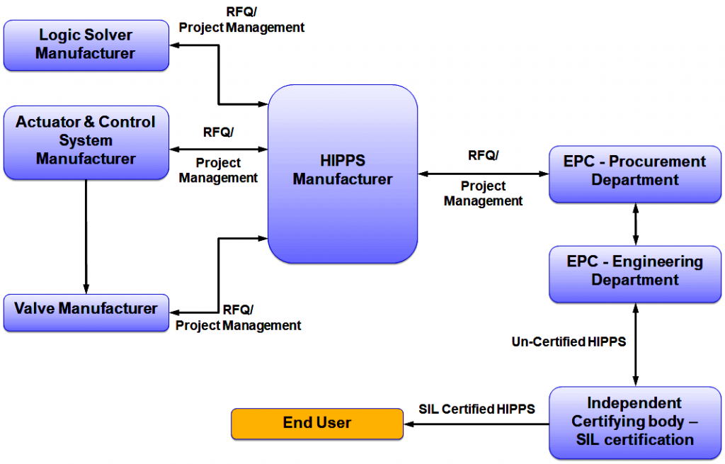
The EPC procurement team has to perform an additional task of project management to ensure all associated items in the bill of quantities (BOQ) are received and handed over to the engineering team. The integrated HIPPS components would then require a SIL certification by an independent certifying body for SIL 3 requirements before being implemented at the End User’s facility.
The disadvantage of employing multiple suppliers causes increased lead time as well as procurement costs. An alternative would be to source HIPPS from a single manufacturer who can provide all individual components and have it certified by an independent SIL certifying body. This reduces the lead time required for procurement as well as the costs associated.