To familiarize the workforce with ongoing Hydro Testing, Pneumatic Strength Testing, Line Blowing & Filling activities (Pressure Testing) safely All pressure and leak testing must have competed in accordance with the Procedure and Safe Work Method and Formal records of pressure and leak testing are maintained and kept and Work carried out by only qualified and experienced persons. in this article, we will summarize the safe procedure of Pressure testing including hydro and pneumatic test safe Distance Calculation
Use pressure Testing checklist

The person in Charge’s Responsibilities are as follows:
- All equipment, plant, and devices used for pressure and leak testing are properly rated, adequately calibrated, maintained, and checked.
- Arrange spill storage.
- PTW precautions are followed.
- Barricade the testing area to control unauthorized entry.
- All personnel should be communicating about starting these activities preferably through the PA system.
- Only essential personnel are allowed access to the test area, only after pressure has been held for a reasonable period.
Types of Pressure Testing and Leak Testing:
There are many types of pressure and leak testing as :
- Standard Pressure Test (Strength Test) – applied either during project construction or later during the operational phase.
- Leak (Pressure) Testing – usually hydraulic, is performed to prove the pressure tightness of joints, glands, and seats, etc., whenever the integrity of containment is broken, either at hook-up/commissioning or post-operation phase.
- Service Leak Testing – usually using service fluid, the testing method for leaks during the post-operation phase on low-pressure systems.
- Pneumatic Leak Tests – using an inert gas, predominantly on gas producing and on some onshore sites during commissioning and post-operation phases, before the introduction of hydrocarbons.
- Gross (Preliminary) Air Leak Tests – using instrument air up to max. of 8 bar, at hook-up/commissioning to identify large leaks, before performing the standard pressure tests.
Test Mediums:
Pressure test medium could be one of the following :
- Hydraulic – water is the preferred test liquid.
- Pneumatic – shall only be permitted if authorized in writing by the Site Manager or his delegate.
Activity Requirements / Guidelines for pressure testing:
the following Requirments shall be followed during performing pressure testing to ensure a safe work environment or undesired events occures
HYDRO / PNEUMATIC TESTING SAFETY
- As possible so as to minimize the stored energy.
- Materials of construction should have the required ductility (flexibility).
- Ensure risk assessment carried out.
- Check that any attachments unable to withstand the test pressure must be removed.
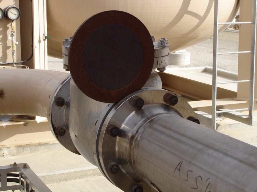
- Blanking devices (spades blinds etc.) shall confirm the required equipment specification.
- Safety valves to be fitted when the pressurizing medium pressure Single, continuous pressure envelope is the preferable method.
- The Responsible Engineer should authorize tests above normal working pressure.
- Persons supervising pressure/leak tests must be trained, competent, and qualified.
- Effective communication should be established.
- Access to the test area must be limited to essential personnel only – barriers, warning signs, PA announcements, patrolling the test boundaries.
- Testing should be carried out under PTW, which is required for each test or at least a test package for the same location.
- Pressuring equipment shall be provided with suitably calibrated pressure control/regulator devices.
- These devices should be clearly visible to the person controlling the pressure.
- Pressuring equipment should not be left unattended at any time during the test.
- When the test pressure has been reached, the pressuring equipment shall be isolated from the equipment under test and where performable disconnected.
- The pressuring valve should be locked in a closed position.
- Ensure the equipment tested by the competent person, prior to testing.
- The volume of equipment under test should be kept as small is greater than the test pressure.
- Slowly-slowly pressure increases.
- Consideration to be given for the change of ambient temperature, e.g. thermal expansion of liquids in a closed system.
- Pressure monitoring to be conducted in any adjacent systems that are not positively isolated.
- Close examination of equipment at above maximum allowable working pressure shall not take place until the pressure has been held for 30 min.
- If an inspection is required within the hold period, then pressure should be reduced to 80% of the test figure.
Hydro & Pneumatic Strength Testing What to Look for:
- Test Pack for line/eqpt. QC complete
- Supervisor & Engineer in place.
- Equipment tested and calibrated (QC reviewed)
- PTW Issued and posted with the M/S (incl. SWMS) at the workplace
- Trained & Competent personnel.
- Toolbox Talk conducted.
- No adjustment whilst under pressure.
- The safe evacuation of test liquids/gases.
- Barriers & Signs in place (agreed distance).
- Patrols around the barrier areas.
- Ensure proper Anchoring arrangements.
- Excavation Entry Gas Test & Checklist.
- The correct level of safety devices.
- Wear face shields during pneumatic testing.
Responsible testing personnel:
- Attend the system at all times.
- Continuously supervision.
Pressure testing equipment:
- Fully operational,
- Regularly maintained,
- Calibrated,
- Warning signs and barriers,
- Caution tags to identify equipment and lines under test,
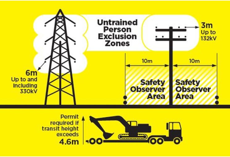
- Maintain a safe distance.
Mechanical isolation used for gas, liquid, or vapor:
Pneumatic testing and very high-pressure hydro-testing conducted when the main test area is free of personnel.
Very high-pressure hydro-testing – use the testing manifold and testing apparatus No alterations or modification permitted without Piping Production Engineer’s approval.
(Read more:E-booksthe-safe-isolation-of-plant-and-equipment)
If there is a failure during the testing do the following:
- Immediately pressure depressurizes.
- Vent valves will open after pressure release.
- find out the Cause of failure and rectified.
In the event of a failure during the pressure test, the system will be immediately depressurized by cracking the vent on the test pump manifold.
After the pressure has been released, the vent valves shall be opened. The cause of failure shall be determined and rectified before any further pressure testing is undertaken.
Hydro testing safe distance formula:
For the Hydro test safe distance
Safe distance = (0.15)x(D)x(a)^0.4x(p)^0.6
where D – Internal diameter (m)
a – Length/diameter of the piece (m)
p – Test pressure (bar)
Safe Distance and Stored Energy Calculator for Piping – Pneumatic Test
Calculate minimum safe distances between the piping system being pneumatically tested and personnel/plant facilities using ASME PCC-2 Mandatory Appendix 501-II and III equations.
The calculation is based on air or nitrogen being used as a test medium with a specific heat ratio of k = 1.4.
To Calculated the Safe distance Click below
[piping_safe_distance_calculator]
For details on the basis of this calculation and example manual calculation refer to the article on Pneumatic Testing – Safe Distances.